For CFD and FEA workloads, cluster design is not just about adding more cores. It is about matching hardware to solver behavior, building the right node types, sizing memory correctly, choosing the right network and storage, and then managing the entire environment in a way that is easy for users and efficient for administrators.
This is especially important because CFD and FEA users do not consume infrastructure in the same way.
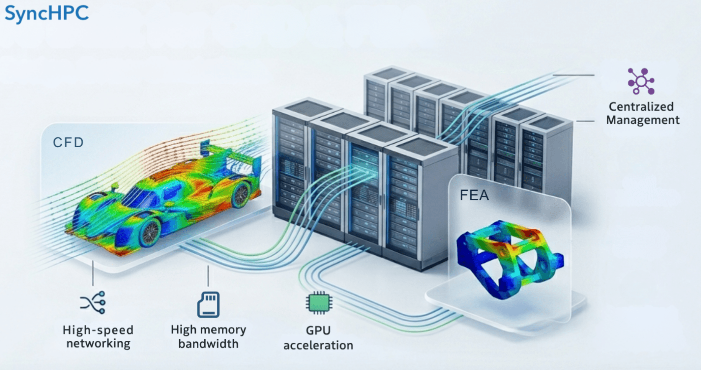
CFD workloads often demand strong parallel scaling, high memory bandwidth, and fast node-to-node communication. FEA workloads, particularly structural and implicit solves, often become more sensitive to memory capacity, memory bandwidth, and I/O behavior of storage as model size grows.
That means a well-designed HPC cluster for engineering cannot be built as a one-size-fits-all compute pool. It should be designed around user profiles, workload classes, bill of materials, procurement discipline, and operational policy with SyncHPC acting as the management layer that turns hardware into a usable engineering platform.
Design separate hardware pools for CFD and FEA
Instead of buying identical nodes for all simulation users, a more efficient design is to build node classes.
CFD Node profile
CFD nodes should prioritize:
- High core density with strong memory bandwidth
- If solver supports GPU compute, then have relevant GPUs like NVIDIA H100/H200/B300 etc.
- Fast and low-latency interconnect (InfiniBand)
- Balanced RAM per core
- Strong MPI performance
For cluster-scale CFD, low-latency networking matters because distributed-memory jobs rely on frequent communication between nodes. NVIDIA’s InfiniBand platform is built specifically around ultra-low latency and high-throughput HPC communication.
FEA Node profile
FEA nodes should prioritize:
- Higher memory capacity per node
- If solver supports GPU compute, then have relevant GPUs like NVIDIA H200/B300 etc.
- Strong memory bandwidth
- Fewer but more effective cores per job when solver scaling tapers
- Fast “local scratch” and robust storage throughput
This is particularly relevant for large implicit, structural, or multiphysics models where memory pressure and disk I/O can become the real limiters. In some cases with availability of more physical memory, simulations can avoid disk I/O and run much more efficiently.
Build the cluster with following Checklist
Below is a reference checklist for a cluster supporting mixed CFD and FEA usage. This is not a final procurement checklist; it is a practical starting point.
Reference BOM: Mid-sized CFD + FEA cluster
A. CFD Compute Pool:
Make sure the the CFD compute pool is according to the CFD node profile.
B. FEA Compute Pool
Make sure the the FEA compute pool is according to the CFD node profile.
C. Optional GPU Pool
- GPU nodes for Compute:
- At the time of writing this post, some of the leading CFD and even FEA solvers already support GPU solver for specific use cases
- In future, multiple solvers will support GPU based simulation. Hence, it is recommended to have at least few nodes with GPU solving capacity (like NVIDIA H200/B300 etc.)
- GPU nodes for Visualization (pre/post processing):
- Sometimes having high-end workstations for every user may not be feasible.
- Users need to download large files to their respective workstations after simulation. This can be avoided with ‘remote visualisation nodes’.
- Remote visualization avoids data copy and data duplication. It also keeps data at centralized location.
- It is recommended to use Nvidia RTX Pro 6000 BSE or NVIDA L40s for visualisation nodes.
D. Storage
- High-performance shared file system backed by SSD / NVMe disks.
- For large clusters with more than 10 compute nodes, it is recommended to have Parallel File System like Lustre.
- The capacity of storage can be defined by understanding the required storage by all users for next 5 years.
- But, generally 80% of this data will be a raw data. Hence, it can be deleted at regular intervals (say monthly). Also, the capacity planning should be done based on this understanding.
E. Networking
- High-speed InfiniBand switch fabric for compute traffic is required.
- Ethernet switch(s) for management traffic
F. Rack and power
- Rack enclosure
- PDUs
- UPS integration
- Cooling planning
- KVM / console access
This type of BOM works because it reflects actual workload behavior: CFD benefits more from fast parallel communication and balanced cores-per-node, while FEA often needs larger memory footprints and more conservative sizing per job. That balance is consistent with Ansys guidance on compute-memory-I/O balance and with HPC networking guidance for tightly coupled distributed workloads.
Buy the Correct BOM
Many HPC projects fail at the procurement stage because the BOM is technically complete but operationally wrong.
A correct BOM should be purchased only after validating:
- Which CFD and FEA solvers will run
- Typical mesh size or model size
- Average and peak concurrent users
- License limits
- Whether jobs are mostly single-node or multi-node
- Expected growth over 3-5 years
- Storage retention policy
- Remote visualization needs
For example, buying only dense CPU nodes may look cost-efficient, but it can become a poor fit if FEA users routinely require high memory per job. Likewise, buying large-memory nodes only can be wasteful if most CFD users need scalable MPI throughput rather than oversized RAM.
A better procurement process is:
- Profile workloads
- Define node classes
- Benchmark representative cases
- Freeze BOM
- Purchase in phases if growth is uncertain
Set Usage Policy: Memory per CPU Core Matters
One of the most practical decisions in HPC design is deciding how much memory per CPU core should be available and enforced.
This matters because adding more cores does not always improve simulation time if memory per core drops too low. Ansys notes that each processor core requires additional memory bandwidth, and that balanced CPU-memory-I/O design is critical for performance.
A practical operating policy
As a starting rule for cluster operations:
- CFD queue: reserve roughly 4–8 GB RAM per CPU core
- FEA queue: reserve roughly 8–16 GB RAM per CPU core
- large-memory FEA jobs: schedule onto dedicated high-memory-nodes
- GPU CFD jobs: size around GPU memory and supported solver workflow, not just CPU core count
Those numbers are practical planning heuristics, not universal laws. They should be tuned after benchmark runs on real customer models.
In other words:
- Too few cores can make jobs slow
- Too many cores can waste license, create communication overhead, and reduce efficiency
- Too little memory per core can push jobs into swapping or heavy I/O
The right answer is not “maximum cores,” but balanced cores, memory, and solver fit.
Build the Cluster Correctly
After procurement, cluster build-out should follow a structured path:
Physical build
- Rack and cable all nodes
- Separate management and compute fabrics
- Configure power redundancy
- Validate cooling and airflow
Software build
- Install OS image across nodes
- Configure scheduler
- Configure MPI and fabric drivers
- Mount shared storage
- Install solver environments
- Set up license connectivity
- Implement monitoring and alerting
Validation
- Run network tests
- Run storage throughput tests
- Run single-node and multi-node solver benchmarks
- Validate queue policies
- Validate user access and permissions
The objective is not just to make the cluster operational, but to make it predictable for engineering teams.
Where SyncHPC Fits In
Once the hardware is in place, the real operational challenge begins: how to make this environment easy to consume. This is where SyncHPC becomes critical.
SyncHPC sits above the infrastructure layer and helps turn a hardware cluster into a managed engineering platform. Instead of users dealing directly with fragmented scripts, queues, manual policies, and backend complexity, SyncHPC provides a unified way to manage simulation resources across the environment.
How SyncHPC helps after the cluster is built
User-specific access
CFD users and FEA users can be given different access paths, queues, templates, and policies based on workload type.
Queue and node-class mapping
SyncHPC can map:
- CFD users to CFD nodes
- FEA users to high-memory-nodes
- GPU users to GPU-enabled resources
- priority users to reserved partitions or policies
Policy-based scheduling
Memory-per-core policies, project quotas, team-level restrictions, and workload classes can be standardized instead of manually enforced.
Unified job submission
Users can submit, monitor, and manage jobs through a centralized interface rather than dealing with fragmented infrastructure operations.
Hybrid extension
If on-prem resources are full, organizations can extend selectively into cloud resources while maintaining a unified management layer. So, while the BOM and hardware design determine the raw capability of the cluster, SyncHPC determines how effectively that capability is delivered to engineering teams.
Conclusion
Designing an HPC cluster for CFD and FEA applications is a hardware problem first, but not a hardware problem only.
It requires:
- Identifying CFD and FEA user behavior separately
- Building the right node types
- Sizing memory per CPU core correctly
- Purchasing the right BOM
- Validating build quality with benchmarks
- Managing the entire environment with a platform that keeps operations efficient
That is the real value of SyncHPC. It does not replace the need for a well-designed cluster. It makes that cluster usable, governable, and scalable for real engineering teams.

Leave a comment